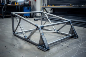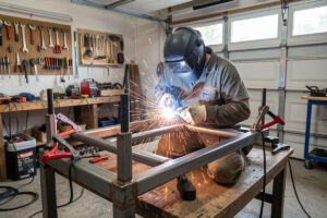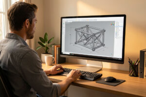
Design your sim rig in CAD before you cut a single tube — an evening at the keyboard saves a weekend at the grinder. A dimensioned 3D model gives you an exact cut list so you cut once, lets you check your real seating ergonomics before anything is permanent, and catches the mistakes that in steel cost angle-grinder time instead of a 30-second hex-key adjustment. I model every rig in Fusion 360 first, and the one time I skipped it, I paid for it.
Steel is unforgiving in a way aluminum profile isn’t. A bolted 80/20 mistake is a reconfiguration; a welded steel mistake is an amputation. That asymmetry is the whole argument for CAD: the cost of a design error in steel is so much higher that spending an evening modeling is obviously worth it, even if you’ve never touched CAD before. And you don’t need to be a mechanical engineer — you need to draw tubes to length, put them where your body wants them, and read off the cut list. Here’s how I do it and which software actually fits a rig build.
Why Bother Modeling a Rig Before Cutting?
Three concrete payoffs: an exact cut list, verified ergonomics, and caught interferences. The cut list means you buy the right amount of steel and cut each tube to the right length and miter angle the first time. The ergonomics check means your wheel, pedals, and seat end up where your body actually wants them. And the model catches parts that would collide — a pedal deck that fouls the seat, a monitor arm that hits the wheel.
The ergonomics payoff is the one people underrate until they’ve lived with a bad rig. In CAD I can set my real seating position — seat height, back angle, distance to the wheel, pedal-deck angle and height — and check it against a rough mannequin or just my own measured dimensions before committing anything to steel. The first steel rig I built without CAD, I set the wheel deck 40 mm too high because it looked right on the bench, and I raced with a cramped, shoulders-up position for a month before I gave up, ground the deck off, and redid it. That whole month of discomfort and the redo would have cost me twenty minutes in a model. Ergonomics is the part of the welded steel rig build that CAD protects best, because it’s the part that’s most expensive to fix in steel.
What CAD Software Should You Use for a Sim Rig?
For most builders, Autodesk Fusion 360 on the free personal-use license is the sweet spot — full parametric 3D, easy to learn, and it generates cut lists cleanly. If you want fully free and open source, FreeCAD does the job with a steeper learning curve. For quick-and-dirty, even SketchUp works if you’re disciplined about dimensions.
I use Fusion 360’s personal license because it’s genuinely free for hobby use, the tube-modeling workflow is fast once you learn it, and the parametric approach means I can change one dimension — say, lengthen the whole frame 50 mm — and the whole model updates. If you object to a cloud-tied Autodesk account, FreeCAD is fully open source and local; it’s less polished but completely capable of a frame this simple. The point isn’t the software, it’s the discipline of dimensioning every tube before you cut. Here’s how the common options stack up for a rig build.
| Software | Cost for hobby | Learning curve | Cut list | Best for |
|---|---|---|---|---|
| Fusion 360 | Free (personal) | Moderate | Yes, clean | Most builders |
| FreeCAD | Free (open source) | Steeper | Yes | Open-source, local-only |
| Onshape | Free (public docs) | Moderate | Yes | Browser-based, any OS |
| SketchUp | Free (web) | Gentle | Manual | Quick visual layouts |
| Pen and graph paper | Free | None | By hand | Simple frames, no 3D |
Honestly, even careful pen-and-paper with a scale drawing beats no plan at all. The failure mode isn’t “wrong software,” it’s “eyeballed it on the bench.” Any method that forces you to commit dimensions before cutting is doing its job.
How Do You Turn a Model Into a Cut List?
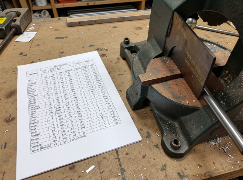
Once the frame is modeled, you extract every tube’s length and end-miter angle into a simple list, then cut to it. In Fusion 360 the measure tool or a timeline of the sketches gives you each length; I write them into a table taped to the wall by the chop saw. Cut every piece before you weld anything, lay them out to confirm they match the model, then start tacking.
My workflow: model the frame with the tube sizes I’ve chosen — 40×40×2 for the structure, matching the sizing logic from choosing steel tube size and wall thickness — then work through the model tube by tube, writing down length and any miter angle. A frame with square-cut butt joints is simplest; mitered corners look cleaner but demand precise angles, which is exactly where the model earns its keep. I cut everything first, dry-fit the whole frame with clamps and no welds, and check it against the model before committing. If a tube’s wrong, it’s a $3 offcut, not a welded-in mistake. Then it goes to the welding table, and the MIG welding walkthrough takes over.
Can You Prototype Parts Before Committing to Steel?
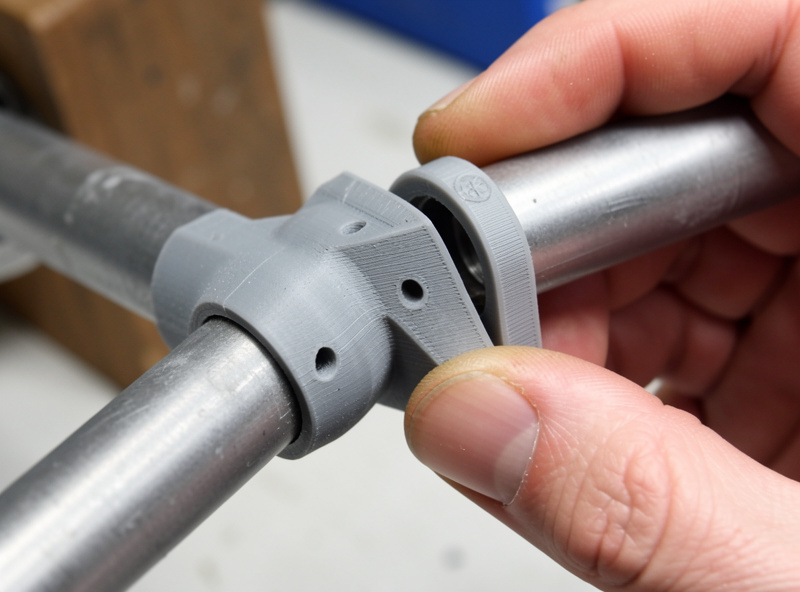
Yes, and it’s one of the best uses of a printer alongside a welder. I print plastic test jigs from the same CAD model to check a joint’s geometry, a bracket’s fit, or a mount’s clearance before I cut or weld the steel version. A printed jig that costs an hour and a few grams of filament can save you a mis-welded joint that costs an afternoon.
This is where the build-it toolkit really compounds. The CAD model that defines the steel frame also defines the bolt-on brackets, button-box plates, and wheel-side mounts, and those I print rather than fabricate, on the same 3D-printing bench I keep for exactly this crossover. Before I weld a tricky joint, I’ll print a small plastic jig that holds the two tubes at the right angle so I can tack them accurately — cheaper and faster than getting it wrong in steel. And because the brackets come straight from the same model, they fit the frame perfectly the first time. The plastic parts handle adjustment and light duty; the steel handles the load path, exactly the division I lay out in bolt-on vs welded sim rig joints.
Which Ergonomic Dimensions Should You Nail Down First?
Five numbers decide whether the rig fits you: seat back angle, seat height off the floor, distance from seat to wheel center, wheel-center height, and pedal-deck angle. Get these right in the model and the rig will feel like it was built around you, because it was. Get them wrong and no amount of stiffness makes it comfortable.
I set them in a deliberate order in CAD. First the seat back angle — I run mine fairly upright, around 15 to 25 degrees back from vertical, because a laid-back GT position tires my neck over a long stint; formula-style builders go far more reclined, and the model lets you try both before you commit. Then seat height, which sets how your legs meet the pedals. Then the wheel: its distance from your chest and its center height relative to your shoulders, because a wheel that’s too high forces your arms up and burns out your shoulders, which is exactly the mistake I welded into my first rig. Finally the pedal-deck angle, which for a load-cell brake I set steeper than most people expect so my foot presses into the pedal rather than sliding down it.
The one dimension people forget to model is monitor position, because it drives your field-of-view math and your eye distance. A correct FOV depends on how far your eyes sit from the screen, and that distance is fixed by where the monitor mounts on the frame — so I rough it into the model too, then finalize it against my monitor mounting and FOV guide. Modeling the screen position also catches the classic interference where a triple-monitor stand’s center upright collides with the wheel at full lock. Better to find that on screen than after the steel is welded.
None of these numbers are universal — they depend on your body and your driving style, which is the whole point of modeling them rather than copying someone else’s dimensions off a forum. A rig built to a stranger’s measurements fits like a stranger’s shoes. Spend the twenty minutes to set your own, and the frame you weld will be the one you actually want to sit in for a three-hour endurance race.
Frequently Asked Questions
Do I really need CAD to build a steel sim rig?
You need a dimensioned plan, and CAD is the easiest way to make one. Steel is unforgiving, so a design error costs angle-grinder time rather than a quick adjustment. A model gives you an exact cut list, lets you verify ergonomics before anything is permanent, and catches parts that would collide. Even careful scale drawing on paper beats eyeballing it on the bench.
What is the best free CAD software for a sim rig?
Autodesk Fusion 360 on its free personal-use license is the sweet spot for most builders: full parametric 3D, a reasonable learning curve, and clean cut-list output. FreeCAD is a fully open-source, local alternative with a steeper curve, and Onshape runs in any browser. The discipline of dimensioning every tube matters more than which one you pick.
How do I get a cut list from my CAD model?
Extract each tube’s length and end-miter angle from the model into a simple table, then cut to it. In Fusion 360 the measure tool gives you each length. Cut every piece first, dry-fit the whole frame with clamps and no welds to confirm it matches the model, then start tacking. A wrong tube caught at dry-fit is a cheap offcut, not a welded-in mistake.
Can I 3D print parts for a steel sim rig?
Yes. The same CAD model that defines the steel frame defines the bolt-on brackets, button-box plates, and mounts, which you can print rather than fabricate. You can also print plastic test jigs to check a joint’s angle or a bracket’s fit before cutting or welding steel, which saves you from expensive mistakes in metal.
How long does it take to model a sim rig in CAD?
For a simple frame, an evening once you know the basics of the software. The first rig takes longer because you are learning the tools at the same time, but the time is trivial next to what a design error costs in welded steel. Budget a few hours, and treat it as insurance against a month of racing in a cramped, wrong seating position.