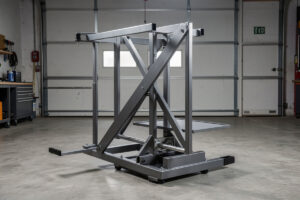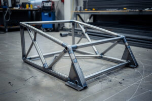
Want a sim rig a local welder will quote at $200 instead of $800? Hand them a dimensioned drawing in 1.5″ square × 0.083″ wall tube where every joint is a single-plane miter at 0°, 15°, 30°, or 45° — no compound copes.
That’s the spread I learned the hard way: a sim rig built around single-plane miter cuts on uniform 1.5-inch square steel tube — the same material spec used for go-kart frames, sold against ASTM A500 Grade B for cold-formed welded structural tubing — runs about $3 per foot at any steel supplier. A 6-foot rig frame uses roughly 40 feet of tube for $120 in raw material. The labor delta between a buildable design and a CAD-art fantasy is whether every joint is one chop-saw pass or a compound-angle cope that demands a tubing notcher and an hour of fitting per joint.
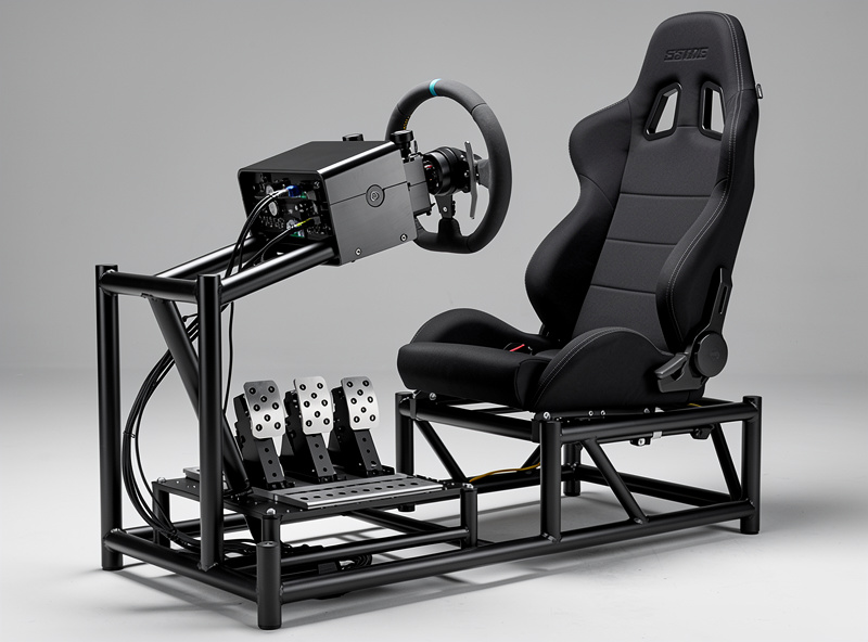
I have designed this rig in Fusion 360 with every joint a single-plane miter cut at 0, 15, 30, or 45 degrees — no compound angles, no tube coping, no bends. This is not because the design looks better; it is because a welder with a chop saw and a MIG machine can cut and fit every joint in under 3 hours. If you want the full build walkthrough for the rig frame — including the aluminum-profile alternative if steel is not your material — start with the DIY sim racing rig build guide, then come back here for the welding handoff. The welding side — the actual MIG technique, settings, and joint welding sequence — lives on homewelder.com’s welding for beginners guide, where machine setup, technique, and safety are covered in detail. What this article covers is the design-to-fabrication handoff: how to create a sim rig design that a local welder can build without asking you to redesign it.
The Rules That Make a Rig Weldable
A sim rig design built for welding follows four rules that most first-time rig designers break:
- Single-plane joints only. Every tube-to-tube connection should be a flat miter cut that a chop saw can make in one pass. A compound-angle joint — where the tube meets at both a horizontal and vertical angle — requires a tubing notcher, a belt sander for coping, and 15–30 minutes of fit-up per joint. A rig with 8 compound-angle joints adds 2–4 hours of labor that a welder will charge for.
- One tube size throughout. Using 1.5-inch square tube for the entire frame means the welder sets the chop saw once and cuts every piece without changing the blade angle or the stop. Mixing tube sizes — 1.5-inch for the base, 1-inch for the wheel deck, 2-inch for the monitor stand — forces the welder to change the saw setup between every piece, which doubles or triples the labor time. If you are still deciding between a welded steel rig and an 80/20 aluminum profile frame, the 80/20 aluminum profile rig guide covers the bolt-together alternative with the same stiffness targets and a different build-skill requirement.
- Gusset plates instead of extra tubes. Diagonal bracing with flat plate gussets (1/8-inch steel, laser-cut or plasma-cut) is faster to weld than a diagonal tube that needs to be coped to fit around existing joints. A gusset plate welds flat against two tubes in 2 minutes per side. A diagonal tube requires cutting, coping, fitting, and welding in 10–15 minutes per end.
- Bolt-together subassemblies. If the rig is wider than a standard doorway (32 inches), design it as two bolt-together halves. A welder cannot deliver a 48-inch-wide welded frame through a 32-inch door. Two halves joined with four bolts through welded-on flanges solve the delivery problem before it becomes one. If you are still deciding whether a full welded rig makes sense for your space versus a folding wheel stand, the sim racing cockpit and stand guide compares rigidity, footprint, and cost across the whole range.
The Mistake I Made on My First Rig
The first CAD I sent a welder had the seat-mount cross-member welded inline with the pedal-box stanchion — fillets stacked on the same face of the tube. It looked clean. Three weeks in, with the direct-drive wheel base pulling about 8 Nm on hard braking, the seat-mount weld cracked at the toe — right inside the heat-affected zone of the inline pedal-box weld. The HAZ had already taken the heat hit; the second structural fillet had nowhere to go. Lesson, paid in regrinding: stitch welds offset from load paths, never inline, never two fillets in the same HAZ. While the frame is bare steel and the welds are still warm is also the right time to plan where every USB cable, pedal wire, and Ethernet line will run — the drill-press pass that cuts routing holes before paint saves rework later, and the sim racing rig cable management guide has the layout I settled on after three teardowns.
The Cut List and the Drawing
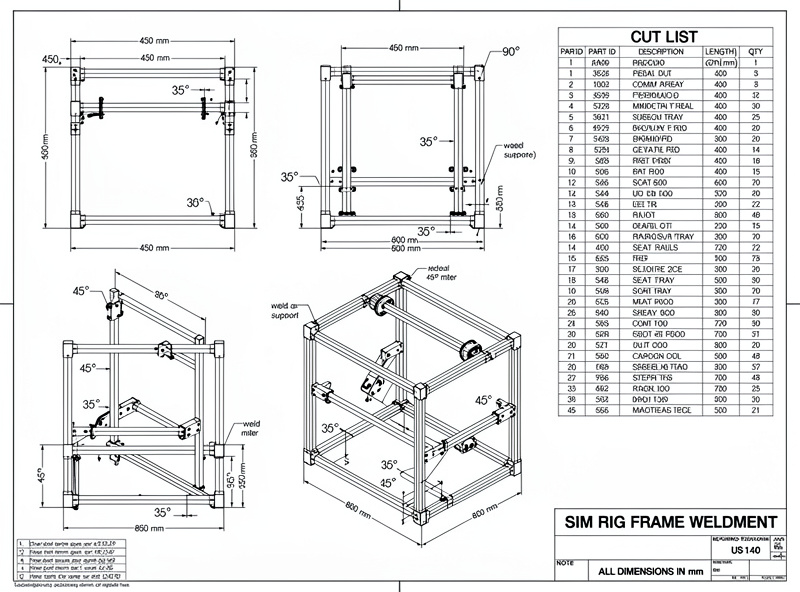
The minimum deliverable from designer to welder is a dimensioned 2D drawing and a cut list. The drawing shows the overall dimensions, every joint angle, and where gusset plates go. The cut list is a table with part numbers, quantities, tube lengths, and miter angles:
| Part | Qty | Tube Size | Length | End 1 | End 2 |
|---|---|---|---|---|---|
| A1 | 2 | 1.5 in sq × 0.083 | 48 in | 90° | 90° |
| A2 | 3 | 1.5 in sq × 0.083 | 24 in | 90° | 90° |
| B1 | 2 | 1.5 in sq × 0.083 | 36 in | 90° | 15° |
| B2 | 2 | 1.5 in sq × 0.083 | 18 in | 15° | 15° |
| G1 | 8 | 0.125 in plate | 4 × 4 in | — | — |
A welder with this cut list and a chop saw can produce every piece in under an hour. If the drawing specifies “all welds: MIG, 0.030 ER70S-6 wire, C25 gas, stitch weld 1-inch every 4 inches on non-cosmetic joints,” the welder knows exactly what machine settings to use without asking. A drawing that says “weld it together” means the welder will call you three times during the build and the rig will cost 30% more.
What the Standards Actually Say
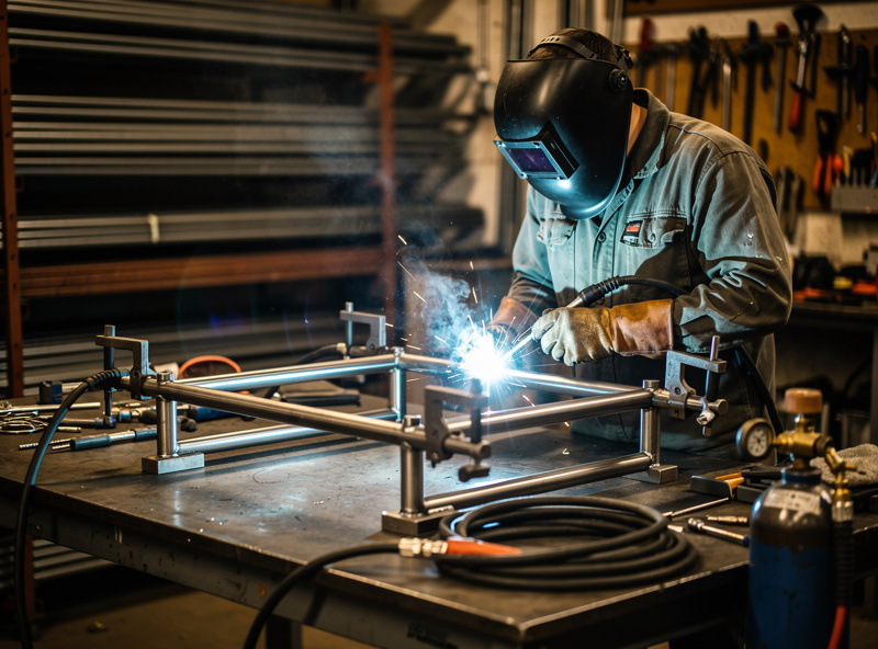
Two published specs do most of the work here. AWS D1.1’s minimum-fillet-weld-size table (Structural Welding Code — Steel) calls for a 1/8-inch fillet on material 1/4 inch and under — which is exactly where a sim rig’s 0.083-inch wall sits, and why a 1-inch stitch every 4 inches on a 1.5″ square HSS is a defensible spec rather than a guess. Worth knowing before you write it on the drawing: the code also allows the actual weld size to run down to the thickness of the thinner part joined, provided fusion is adequate — so a welder running that 1/8-inch call on 0.083″ wall should be dialing in enough preheat and travel speed to get full fusion without blowing through, not just laying down the biggest bead the gun will make. For the full build sequence — jig setup, tack-weld order, and how to check square before burning every joint — the sim racing rig build guide walks through every step on the welding floor. ASTM A500 is the spec the steel itself is sold against: Grade B cold-formed welded structural tubing has a minimum yield of 46 ksi for square and rectangular shapes (42 ksi for round — the shape matters to the number), which is what makes 0.083″ wall stiff enough for a direct-drive wheel base. Print “ASTM A500 Gr. B, 1.5 in sq × 0.083 wall” on the cut list and the steel supplier knows exactly which bin to pull from. Print “1.5 inch tube” and you might get welded round tubing in mystery alloy.
What a Good Weld Looks, Sounds, and Feels Like
Pick up 4 feet of 1.5″ × 0.083″ wall and you can twist 2–3 mm of flex into the ends. The same length in 0.120″ goes inert through the gloves. A clean MIG stitch in 0.030″ ER70S-6 with C25 lays a dull-grey stack-of-dimes with a faint bacon-hiss; the same joint in flux-core gives popcorn porosity across the bead. When the wheel base hits a curb mid-race, a sound weld stays silent — a cold joint makes a metallic tick.
Sequencing the Welds So the Frame Stays Square
A design that is buildable on paper still warps in the shop if the welder burns every joint in drawing order, corner to corner. Heat shrinks the weld pool as it cools, and if every pass goes down on the same side of the frame before the other side gets any heat, the whole assembly bows toward the welded side by the time you are done — sometimes enough that the rig no longer sits flat on all four feet. The standard fix, and the one I have my welder follow every time, is a skip-weld pattern: tack every joint square first, check diagonals with a tape measure corner to corner (equal diagonals mean square), then weld opposite joints in an alternating sequence so the heat input balances across the frame instead of pulling it one direction. On my rig, that meant welding the front-left and rear-right joints, letting them cool to the touch, then the front-right and rear-left, rather than working around the perimeter in one pass.
This is also where a cheap fixture pays for itself. Even two adjustable saw-horses with a piece of angle iron clamped across them to hold the base tubes square during tacking will catch most of the warp that an unclamped tack-and-weld sequence introduces. If your welder is quoting the job cold, mentioning that you will have the frame tacked-and-checked-square before final welding — or that you expect them to — is worth putting on the drawing as a note, not just assuming it happens. It costs nothing to write “verify diagonals equal before final weld pass, tolerance 1/16 inch” in the corner of the drawing, and it is the single cheapest insurance against picking up a finished rig that rocks on three feet instead of sitting flat on four.
Frequently Asked Questions
How much does it cost to have a sim rig welded?
A simple single-plane miter-cut rig with 10–12 joints costs $150–300 in labor at a typical fabrication shop. A compound-angle coped-tube rig costs $400–800. The material for a 1.5-inch square steel tube rig frame costs $80–150. Total cost for a welded rig is $230–450 for a simple design plus material.
Can I design a sim rig without knowing how to weld?
Yes. The design is CAD work — you do not need to know how to weld to produce a dimensioned drawing and a cut list. What you do need is to understand which joints are simple miter cuts and which are compound angles, so the design is buildable. The welder brings the fabrication knowledge; you bring the dimensional spec.
What tube size should I use for a sim rig frame?
1.5-inch square steel tube with 0.083-inch wall thickness is the standard for sim rigs and go-kart frames. It is stiff enough for a direct-drive wheel base (no flex at 20 Nm of torque), light enough that one person can move the rig, and affordable at $3 per foot. 1-inch tube flexes under a direct-drive wheel. 2-inch tube is overkill and adds weight without stiffness benefit.
Do I need TIG welding for a sim rig or is MIG fine?
MIG welding is the correct process for a steel tube sim rig. It is faster (3–4× faster than TIG on steel tube), stronger in this application (MIG fillet welds on 0.083-inch wall tube are stronger than the tube itself), and every fabrication shop has a MIG welder. TIG is for aluminum, stainless, and cosmetic welds — none of which apply to a painted steel sim rig frame.
Should I paint the rig before or after welding?
After. Welding burns off paint in a 1–2 inch radius around every joint, and the burned paint contaminates the weld puddle (porosity, inclusions, weak joints). Weld the raw steel, wire-brush the welds, wipe with acetone, then paint. A rattle-can of Rust-Oleum satin black covers a 6-foot rig frame with two coats for $15.
How do I get a welder to take a small sim rig job?
Small fabrication shops, muffler shops, and independent welders on Craigslist or Facebook Marketplace take one-off jobs in the $150–400 range. Bring the cut list, the dimensioned drawing, and the steel already purchased. A welder who only has to cut and weld is much more likely to say yes than one who has to source material and interpret a vague sketch.