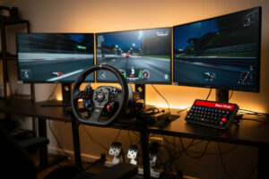
A DIY sim racing button box is one of the cheapest, most satisfying upgrades you can make: about $40–$80 in parts buys a 16-input panel with rotary encoders that a pre-built would charge $120–$200 for. The whole build is a controller board, switches, encoders, wire and an enclosure — and it presents to the game as a plug-and-play USB controller with no drivers.
I’ve built three of these. The first was rough, the third looks like it came from a vendor, and the lesson between them was that the electronics are easy — it’s the layout planning and the enclosure that separate a good box from a frustrating one. This is the full build, the way I’d hand it to someone standing at my bench. For the broader picture of where a box fits your cockpit, start with the button box guide.
The full parts list
You need five things and nothing exotic: an ATmega32U4-based controller board, your switches, two or three rotary encoders, hook-up wire, and an enclosure. Budget around $50 for a clean 16-input box. Everything here is generic — there’s no proprietary part that locks you in.
The controller is an Arduino Pro Micro or Leonardo (the 32U4 chip natively shows up as a USB joystick). Switches: SPST toggles for on/off functions, momentary push buttons for one-shots, optionally a covered toggle for ignition. Encoders: EC11-type rotaries for TC, ABS and brake bias. Wire: 22–24 AWG stranded. Enclosure: a 3D print, a project box, or an aluminium plate. As an Amazon Associate I earn from qualifying purchases. Useful searches: a Pro Micro board, EC11 rotary encoders, and a switch and button assortment.
| Part | Spec | Rough cost |
|---|---|---|
| Controller board | Arduino Pro Micro (ATmega32U4) | $8–$15 |
| Toggle/momentary switches | SPST, 6mm/12mm panel mount | $10–$20 |
| Rotary encoders | EC11 with detents, ×2–3 | $6–$12 |
| Hook-up wire | 22–24 AWG stranded | $5 |
| Enclosure | 3D print / project box / alu plate | $0–$20 |
| USB cable | Micro-USB, braided | $5 |
Plan the layout before you drill a hole
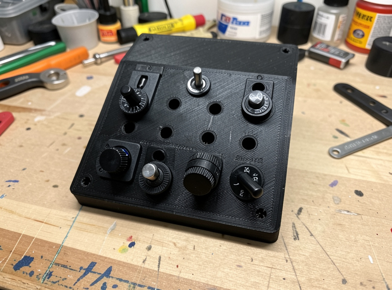
Decide every function and its position on paper first, because a button you placed wrong is a hole you can’t un-drill. Group by how often you touch a control and by muscle memory: ignition and starter together, lights and wiper as a cluster, rotaries where your fingertips fall without leaving the wheel.
On my deck the right-hand third carries the rotaries — TC, ABS, brake bias — because those change mid-stint, while the one-shot stuff (pit limiter, reset, MFD) lives left where a mistaken press costs nothing. Sketch it at 1:1 scale, hold your hand over the paper in your seating position, and only then commit to drill positions. This single step is what made my third box feel designed rather than assembled. My first box failed exactly here: I drilled the layout to look symmetrical instead of to match my hand, and the ABS dial ended up a reach away that I never actually used mid-corner — a wasted encoder I had to live with until I rebuilt the deck from scratch.
Wiring: the common-ground matrix
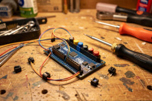
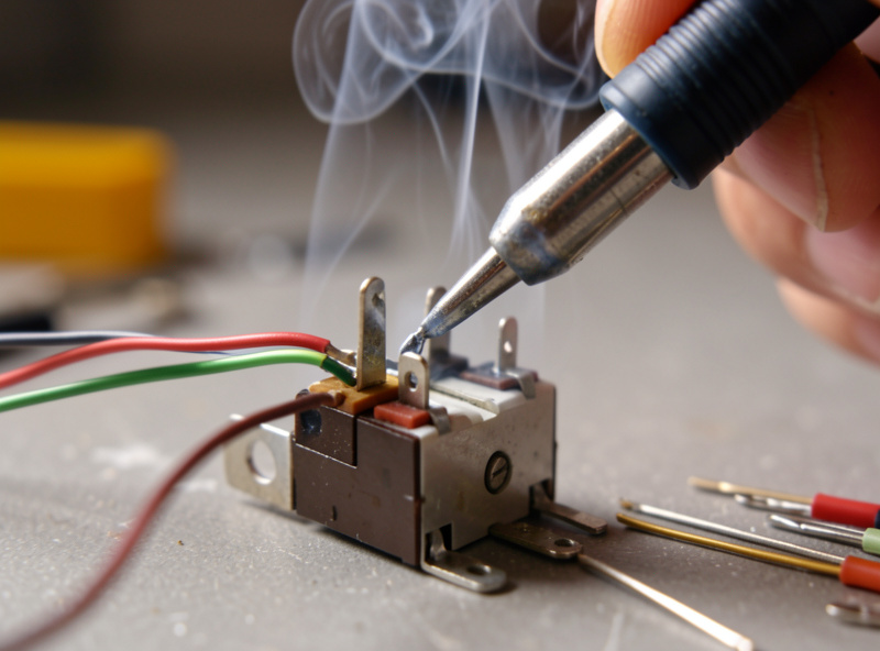
Every switch shares one ground wire daisy-chained between them, and each switch’s other leg runs to its own digital pin on the board — that’s the entire wiring concept. One common-ground bus, one signal wire per input. Encoders are the exception: each needs two signal pins plus the shared ground.
Run a single ground wire from the board’s GND pin and link it switch-to-switch in a chain, leaving a short pigtail at each. Then run an individual signal wire from each switch’s second terminal to a free digital pin. Keep the runs short and consistent, and label both ends with tape before you solder — future-you debugging a dead button will thank present-you. The detailed wiring walkthrough, including encoder pinouts and strain relief, is in the wiring guide.
Flashing the firmware
The board needs firmware that maps each pin to a joystick button — the standard route is Arduino IDE with the Joystick library, and for encoders a small sketch that reads each detent as a momentary “increment” or “decrement” press. Once flashed, Windows sees a generic game controller and every input shows up in the game’s controls menu.
The encoder handling is the part worth getting right: a raw EC11 fires two state changes per click, so your sketch must debounce and emit a single clean pulse per detent or your traction-control dial jumps two notches. If firmware isn’t your thing, this is exactly the trade-off that pushes people toward a pre-built — laid out fully in the Arduino vs pre-built comparison. The encoder behaviour itself is covered in the encoder wheels guide.
Mounting it to the rig
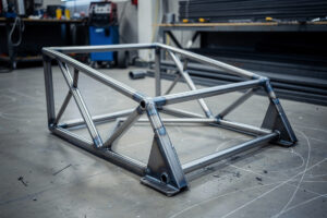
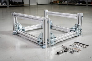
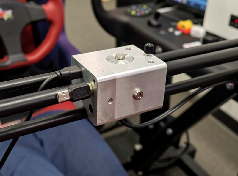
A button box that flexes or slides under a firm press is worse than none — mount it rigidly where your hand falls without leaving the wheel. On my welded rig that’s a 3D-printed bracket clamped to an aluminium profile rail just inside the right of the wheel, angled toward the seat.
If you’ve got a printer, a custom bracket is the obvious move — the same printer that does my rig brackets does the button-box plate. If not, a length of profile rail and a couple of brackets, or even sturdy double-sided VHB tape on a flat deck panel, will hold a light box fine. The mounting logic mirrors the rest of the cockpit: rigidity first, comfort second, looks last. The cockpit and stand guide covers where panels like this attach on different rig types.
Sizing the box to your board’s pins
Before you finalise the layout, count your inputs against the controller’s available digital pins, because that’s the real limit on how big a box you can build on one board. A Pro Micro offers a modest number of usable pins, switches take one each, and encoders take two each — so the maths adds up faster than beginners expect.
A practical first box is around 12 switches plus two encoders, which fits a single Pro Micro comfortably with room for the encoders’ extra pins. If you want a wall of 20-plus inputs, you either step up to a board with more pins, add a multiplexer chip to expand them, or accept a second board. For most people the sweet spot is the dozen-or-so inputs that cover every common in-car function anyway, so the pin limit and the useful-input count line up nicely. Plan this on paper alongside your layout sketch — a hole you can’t wire is as wasted as a hole in the wrong place.
Binding and testing in-game
Plug in, open Windows’ “Set up USB game controllers” to confirm every input registers, then bind them in-game one at a time. Test the box in Windows first — it isolates a wiring fault from a binding mistake before you’re confused in the sim. A dead button in the Windows tester is a solder problem; a dead button only in-game is a binding problem.
In iRacing and ACC the controls menu lets you click a function and press the physical input to bind it. Do ignition, starter and pit limiter first, then the rotaries, then the rest. Once bound, the box becomes invisible in the best way — you stop thinking about it and just drive eyes-up. Pair it with sorted force feedback and you’ve removed two of the biggest distractions from a clean lap. If this is your first build, do it in this order: plan the layout on paper, wire and flash the board before you mount anything, and test every input in Windows before you ever load the sim — get those three habits right on box number one and you will skip the rough first attempt I had to learn from.
Frequently Asked Questions
How much does it cost to build a sim racing button box?
A clean 16-input DIY button box with rotary encoders costs roughly 40 to 80 dollars in parts: about 10 dollars for the board, 10 to 20 for switches, 6 to 12 for encoders, plus wire and an enclosure. That undercuts a comparable pre-built by half.
What Arduino board is best for a button box?
Any ATmega32U4 board such as the Arduino Pro Micro or Leonardo, because the 32U4 chip natively presents as a USB HID joystick with no extra drivers. Avoid the Uno or Nano for this, as their chips do not do native USB HID easily.
Do I need to know how to solder?
Yes, basic soldering. You are joining wires to switch terminals and board pins, which is beginner-level work. If you would rather not solder at all, a pre-built button box is the better route and only costs a little more.
How do I stop rotary encoders jumping two settings per click?
A raw EC11 encoder fires two state changes per detent, so your firmware sketch must debounce and emit a single increment or decrement pulse per click. Most Arduino joystick encoder libraries handle this with a one-line setting.
How do I mount a homemade button box to my rig?
Mount it rigidly where your hand falls without leaving the wheel, usually on a bracket clamped to an aluminium profile rail beside the wheel. A 3D-printed plate is ideal; profile brackets or strong VHB tape work for a light box.